Designed in accordance with the European standard EN12527 1999 and the national standard GB/T 14687-2011, it can conduct "dynamic tests", "long-distance walking tests", and "static load tests", with t ...
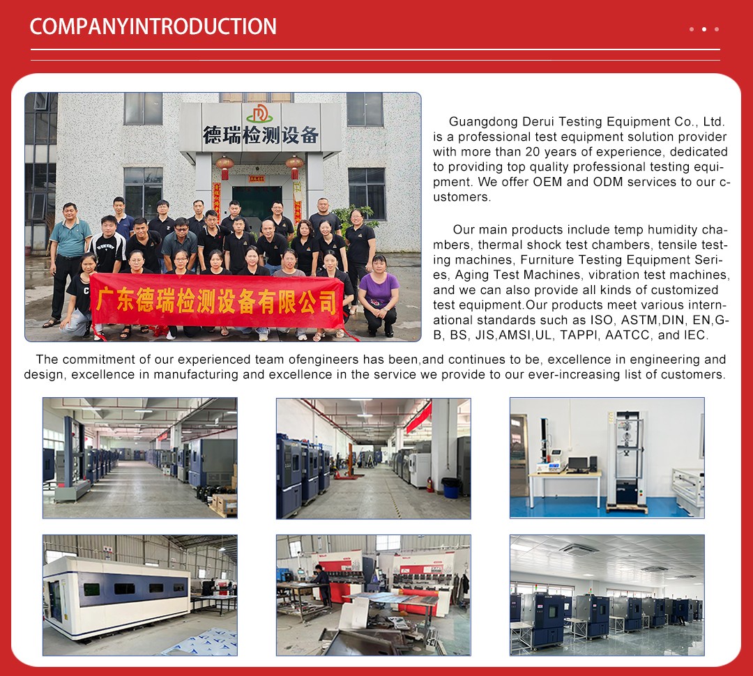
Designed in accordance with the European standard EN12527 1999 and the national standard GB/T 14687-2011, it can conduct "dynamic tests", "long-distance walking tests", and "static load tests", with touch screen control. The caster performance testing machine can perform tests in accordance with various domestic and international quality standards for casters.
Testing items
Long-distance movement test, dynamic test, static load performance test, etc. The load is applied by a hydraulic push rod to exert pressure. The test environment and conditions are simulated.
Touch screen interface functions.
a. Load weight, obstacle height, test result description, etc. are input on the computer interface.
b. The test stroke value is set through the user interface of the touch screen and displayed in real time.
c. The linear speed of the roller is adjusted by the frequency converter, and displayed in real time on the touch screen user interface.
d. Parameters such as speed, number of obstacle crossings, number of wheel rotations, total running time, and total running distance are displayed on the touch screen user interface based on the actual measurement.
e. After starting the machine, it automatically stops when the casters reach the specified stroke value. After stopping, the tester can still print the test report.
f. When the caster is damaged, the testing machine automatically alarms and stops.
Core technologies and configurations
| Item | Parameter Range |
|---|---|
| Installation Caster Diameter | 100~600 mm (space reserved at front of hydraulic push rod for movable installation) |
| Installation Caster Width | Max. 400 mm (drum bearing can withstand thrust or load over 10 tons) |
| Traveling Speed | 1.5 km/h ~ 16 km/h (drum rotation with protection function: if high speed is set initially, speed will slowly increase from 0 to set value in about 20 seconds) |
| Obstacle Strips | Horizontal and parallel, width 100 mm; 6 customizable heights (5 mm, 6 mm, 7 mm, 8 mm, 9 mm, 10 mm), 2 pieces for each size with mounting holes (specifications customizable by customer) |
| Drum Dimensions | Diameter 1 m, drum surface width 600 mm |
| Load Range | Max. load 8 T (push rod can apply 8 T force load to casters via hydraulic pump) |
| Loading Control | Load can be increased randomly at irregular intervals under constant speed (hydraulic loading cylinder designed to be placed horizontally) |
| Drum Pressure Resistance | Drum can withstand pressure over 10 tons; bearing can support rotation under 10 tons without damage |
| Overall Dimensions | Control cabinet: 600×600×1850 mmTest bench: 3700×1750×3000 mm |
Main content
1. The hydraulic push rod of the machine and the fixed part at the bottom of the machine are designed to be movable, in the form of an adjustable hole and a fixed bolt for locking and tightening. The adjustable hole and the fixed bolt must be able to firmly lock under the maximum thrust and maximum load of the hydraulic push rod. Since the test of the casters may involve the upper gear castings of the casters, a larger adjustment space may be required. The bolts used in the hydraulic push rod part must be able to withstand a force of 8 tons without deformation, damage or loosening.
2. The front end of the machine's hydraulic push rod needs to have a connecting fixture for connecting the test drive wheel. The approximate size is a 25 cm square steel plate, with bolt holes at the four corners to connect the front drive wheel. The thickness of the steel plate is 25 mm. The fixture and the hydraulic push rod can be connected by a threaded connection. The steel plate of the fixture must be able to withstand a force of 8 tons without deformation.
3. The test machine has a forward and reverse function, with an interface for input. For example, one cycle is 3 minutes forward, 1 minute stop, 3 minutes reverse, and 1 minute stop. The interface can input the time, set the forward and reverse time and stop time of one cycle, as well as the number of cycles. The interface displays the current pressure of the hydraulic push rod, the thrust load weight, the number of cycles, the roller speed, the oil temperature, and the surface temperature of the caster.
4. The equipment can be used for testing drive wheels or casters.
5. It has an infrared temperature measurement function to test the temperature of the casters, and the caster test temperature needs to be displayed on the interface. The computer automatically records the surface temperature of the wheel every few minutes. For example, if it is set to every 15 minutes, the computer will automatically measure and record the surface temperature of the wheel once, and it will be included in the report at the end.
6. It uses a PLC control system to display the walking distance, tire temperature, number of cycles, etc. (The PLC of the machine must be a Siemens PLC).
7. It has a clock that can be set to start and end the test at a specific time (to control the running time) (the screen displays the load and speed).
8. The set value of the total walking distance should be able to reach 99,999 kilometers.
9. It has a protection device. If the wheel suddenly breaks during the test, the machine can detect it and automatically stop. At the same time, it will record the time when the wheel is damaged. (For example, there is a limit at the connection between the push rod and the caster. When the caster casting breaks, the push rod suddenly loses its position, and the machine will stop for protection. This limit can be adjusted according to different wheels).
10. The same wheel can be tested with different test programs, which can be set on the operation interface. During the test, the speed can be set to change, such as increasing the speed by 10% after 15 minutes. During the test, the load can be set to change, such as starting with a load of 1 ton, automatically increasing to 2 tons after half an hour, and then increasing to 3 tons after another half an hour, until the load reaches 8 tons.
11. Upper roller mechanism: The upper part of the roller needs to have the following test mechanism. Four vertical columns (2.5 meters, diameter 120mm) are fixed perpendicularly to the horizontal plane, and there is a heavy block fixture that can slide up and down. The schematic diagram is as follows. The columns need to be equipped with protective limit blocks, and the heavy block fixture needs to be able to slide smoothly on the columns. The columns need to be able to withstand a load of 5 tons when the bottom caster moves forward.
12. The equipment itself has protection functions, such as stopping the machine when the roller motor overheats, when the surface of the tested caster overheats, when the caster is damaged (severely worn or suddenly broken), and when the oil temperature of the hydraulic push rod is too high.
13. The hydraulic system of the hydraulic push rod itself uses a fan cooling system to protect the hydraulic oil from overheating under high pressure. The fan cooling and the machine itself are interlocked. If the fan cooling stops due to high temperature, the entire machine will be protected and stop.
14. When the equipment is running at the highest power without load, the noise within 10 meters should not exceed 80 dB.
15. The contact area between the machine and the ground has a buffer rubber base. 16. The machine's PLC and computer need to be connected to the Ethernet via a wireless router, and they should be able to communicate with remote computers in the office. Remote monitoring and viewing should be possible, as well as remote calibration and program modification.
Application scenarios and industry value
Industrial casters production: Pre-delivery brake life testing for heavy-duty forklift and warehouse rack casters.
Medical device industry: Low-noise braking durability verification for operating table and hospital bed casters.
Research and development laboratories: Optimization of brake pad materials (ceramic, sintered metal), spring return mechanisms, and dust-proof designs.
Certification testing: Compulsory inspection items such as ISO 22883 brake life and DIN 15106 anti-slip performance.
After-sales service
Warranty Policy: Most manufacturers offer a one-year full machine warranty, and support remote fault diagnosis and operation training.
Customization Service: Customization based on requirements, including custom fixtures and software functions according to test standards (such as JIS/CNS) to meet special needs.
After-sales Service: One-year full machine warranty, providing operation training and remote technical support.
Data Service: Optional cloud data platform for generating CNAS-compliant test reports remotely.
Technical Support: Free remote debugging, operation training, and annual equipment calibration services.
Spares Supply: Quick replacement service for consumable parts (fixtures, hydraulic seals).
Ordering Process
Requirement Communication: Provide test standards and relevant parameters.
Solution Confirmation: The supplier provides 3D drawings and parameter lists.
Production and Delivery: 15-20 days for standard models, 30-45 days for non-standard custom models.
Acceptance and Training: Engineers install and debug on-site and provide on-site training.